Business Hours (UTC+3)
Mon-Fri: 8 AM - 5 PM
Mon-Fri: 8 AM - 5 PM
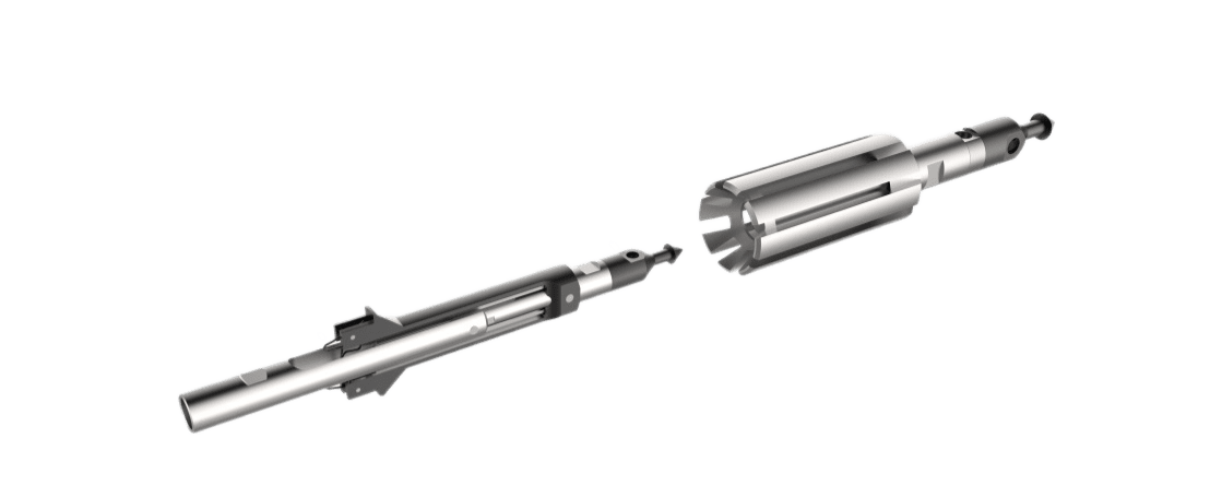
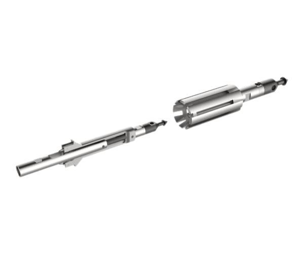
Automatic latching device for downhole gauges
Designed for engaging on permanent dowhole gauges installed in the well at the selected depth followed by retrieval to surface.
By clicking on the button, you consent to the processing of your personal data in accordance with the privacy policy
01
02
Direct equipment manufacturer
We guarantee the quality of our products
Certified equipment
Development according to drawings
Warranty service
Worldwide delivery
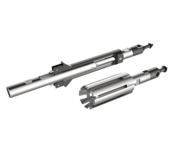
It is used in production, observation and injection oil and gas wells as part of a downhole lubricator equipped with a stuffing box on the tubing ø73 mm, in the process of performing well testing and wireline operations permanent downhole gauges and pressure gauges using a winch on a wire, and when scraping the inner walls of the tubing from asphaltene-resin-paraffin deposits.
- The anchor levers lock and hold the auto-release with the device in the coupling connection at the selected depth
- The trigger holder, together with the wire, detaches from the auto-release and rises to the surface
- The downhole catcher descends on a wire, provides capture and extraction from the tubing of the automatic hook with the device
Operating Principle
Technical Specifications
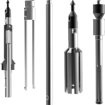
- Anchor for fixing the downhole gauges in the well
- Fork for holding the anchor until actuated
- Weight stem
- Wire/cable attachment (cable head)
- Collet catcher for engaging on the anchor and retrieving it with the gauge to surface
- Expander with nut for removing the anchor
Standard kit
Video Presentation
The depth gauge (15) (see Fig.) is connected to the holder (14) loosely fixed to the adapter (9) by means of an axle (10). The adapter (9) has a catching head and ensures that the holder (14) is suspended from the anchor (11). The anchor (11) is a U-shaped arm with protruding teeth, made of spring steel. The ends of the cantilever have milled slots, within which mirror-image spring wire hooks (13) are located on axles (12) and fastened thereto. A spring fork (8) with protruding teeth is inserted into the holes on the armature (11), onto which the weighting device (7) and the ropsocket (6) are screwed.
The UAPGP works as follows: before running downhole, the cantilever springs of the anchor (11) are brought together with the fork (8) inserted into the anchor and fixed in this position by wire hooks (13) fastened on the axles (12). At the same time, the tines of the fork rest against the end of the adapter (9) and prevent removal of the fork from the anchor, thus ensuring that the entire device is held on the fork to which the wire head is attached. The transverse dimensions of the spring anchor (11) in the compressed state ensure unobstructed descent of the entire assembly into the tubing. Spring wire hooks (13), sliding on the inner surface of the tubing, centre the UAPGP inside the tubing string.
To activate the anchor, the lowering of the FPSO is stopped at the specified depth and lifting is started. At the same time wire hooks (13), having reached the joint of 2 tubing pipes, rest on the annular neck (release by twisting 2 threads) on the inner surface of the tubing coupling and are yanked off the holding axles (12). Anchor spring arms (11) are straightened and the teeth on their outer surfaces fall into the annular groove of the coupling. The spring fork (8), in its turn, also straightens and the teeth on it get out of engagement with the end faces of the adapter (9).
With further upward pulling, the spring fork (8) leaves the anchor (11) and rises on the wire from the borehole.
When the spring fork (8) is undone, the catching head made on the adapter is exposed on the upper end of the anchor. To extract the UAPGP with the depth gauge from the borehole, a collet catcher (see Fig.) is used, consisting of a body (4), a collet clamp inserted into it and a ropsocket (3).
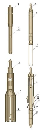
Principle of action
Photo Gallery
FAQs
The device for automatic suspension of depth gauges is designed for 35 MPa pressure.
UAPGP is made in versions for 73 and 89 columns.
Yes, we offer a 1 year warranty on the automatic depth gauge suspension device.
To order equipment and consult with our experts, you can contact us by phone, email or fill out the feedback form on our website. Our team will be happy to help you find a solution optimised for your needs.


